Wednesday 17 October 2018

Basic Electronics Question


Q1.  Expand ECE.

 Electronics & Communication Engineering.


Q2.  What is Electronic?

The study and use of electrical devices that operate by controlling the flow of electrons or other electrically charged particles.

Q3.  What is engineering?

The application of science to the needs of humanity and a profession in which a knowledge of the mathematical and natural sciences gained by study, experience, and practice is applied with judgment to develop ways to use economically the materials and forces of nature for the benefit of mankind.

Q4.  Difference between electronic and electrical.

Electronics work on DC and with a voltage range of -48vDC to +48vDC. If the electronic device is plugged into a standard wall outlet, there will be a transformer inside which will convert the AC voltage you are supplying to the required DC voltage needed by the device. Examples: Computer, radio, T.V, etc... Electric devices use line voltage (120vAC, 240vAC, etc...). Electric devices can also be designed to operate on DC sources, but will be at DC voltages above 48v. Examples: are incandescent lights, heaters, fridge, stove, etc.

Q5. Difference between mobile and a cell phone. 

There is no difference, just language use, which differs from country to country, so in Britain it is called a mobile, and in USA and South Africa and other places a cell phone. Even in Europe the name differs. The Germans call it a "handy", which in English has completely another meaning as an adjective, meaning useful. In Italy it is called a telofonino or "little phone". This difference in British and American English is also evident in many other things we use every day, like lifts and elevators, nappies and diapers, pickups and trucks. The list goes on and on, any student of English has to decide which he or she will use, as the default setting.

Q6. How does a mobile work?

When you talk into a mobile telephone it converts the sound of your voice to radiofrequency energy (radio waves). The radio waves are transmitted through the air to a nearby base station. The base station then sends the call through the telephone network until it reaches the person you are calling. When you receive a call on your mobile phone the message travels through the telephone network until it reaches a base station near to you. The base station sends out radio waves, which are detected by your telephone and converted back to speech. Depending on the equipment and the operator, the frequency that each operator utilises is 900MHz, 1800MHz or 2100MHz. The mobile phone network operates on the basis of a series of cells. Each cell requires a radio base station to enable it to function. There are three types of base station and each has a particular purpose:

1. The Macrocell is the largest type and provides the main coverage for mobile phone networks.
 2. The Microcell is used to improve capacity in areas where demand to make calls is high, such as shopping centres.
 3. The Picocell only has a range of a few hundred metres and may be used to boost weak signals within large buildings.
Each base station can only cope with a certain number of calls at any one time. So if demand exceeds the capacity of a base station an additional base station is needed.

 Q7. What is resistor? 

A resistor is a two-terminal electronic component that opposes anelectric current by producing a voltage drop between its terminals in proportion to the current, that is, in accordance with Ohm's law: V= IR.

Q9.  What is capacitor?

 A capacitor is an electrical/electronic device that can store energyin the electric field between a pair of conductors (called "plates"). The process of storing energy in the capacitor is known as "charging", and involves electric charges of equal magnitude, but opposite polarity, building up on each plate. Capacitors are often used in electric and electronic circuits asenergy-storage devices. They can also be used to differentiate between high-frequency and low-frequency signals. This property makes them useful in electronic filters.
Q10.  What is inductor?

 An inductor is a passive electrical device employed in electrical circuits for its property of inductance. An inductor can take many forms.

Q11.  What is conductor?

A substance, body, or device that readily conducts heat, electricity, sound, etc. Copper is a good conductor of electricity.

Q12.  What is a semi conductor?

A semiconductor is a solid material that has electrical conductivityin between that of a conductor and that of an insulator(AnInsulator is a material that resists the flow of electric current. It is an object intended to support or separate electrical conductorswithout passing current through itself); it can vary over that wide range either permanently or dynamically.

Q13. What is diode? 

In electronics, a diode is a two-terminal device. Diodes have two active electrodes between which the signal of interest may flow, and most are used for their unidirectional current property.

Q14.  What is transistor? 

In electronics, a transistor is a semiconductor device commonly used to amplify or switch electronic signals. The transistor is the fundamental building block of computers, and all other modernelectronic devices. Some transistors are packaged individually but most are found in integrated circuits.

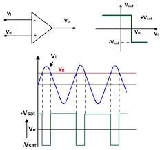
Q15.  What is op-amp?

An operational amplifier, often called an op-amp , is a DC-coupledhigh-gain electronic voltage amplifier with differential inputs[1] and, usually, a single output. Typically the output of the op-amp is controlled either by negative feedback, which largely determines the magnitude of its output voltage gain, or by positive feedback, which facilitates regenerative gain and oscillation.


#IPECElectronics#Tech#Communication#electronicscore
Share:

Monday 3 September 2018

Satellite Communication

SATELLITE COMMUNICATION

In telecommunications, the use of artificial satellites to provide communication links between            various points on Earth. Satellite communications play a vital role in the global tele communications system. Approximately 2,000 artificial satellites orbiting Earth relaynanalog and digital signals carrying voice, video, and data to and from one or many locations worldwide.

Satellite communication has two main components: the ground segment,which consists of fixed          or mobile transmission, reception, and ancillary equipment, and the space segment, which primarily is the satellite itself. A typical satellite link involves the transmission or uplinking of a signal from an Earth station to a satellite. The satellite then receives and amplifies  the signal and retransmitte back to Earth,where it is received and re-amplified by Earth stations and terminals. Satellite receivers on the ground include direct-to-home (DTH) satellite equipment,mobile reception equipment in aircraft, satellite telephones, and hand held devices.  

Click here for the PPT on Satellite communication 


Image result for SATELLITE COM


For more PDF and Question like this stay update on my FB_PAGE and blogger site.


#IPECElectronics#Tech#Communication#electronicscore
Share:

Basic Power Electronics Interview Questions


This post consists of some of the frequently asked Power Electronics interview questions Considering that the Candidate is Fresher and has no hands on experience with him. But these basic power electronics interview questions will be useful for others too to refresh their basics…


Q-1 What is holding current in SCR?

It is the minimum current required to hold the SCR in forward conduction state. When the forward current becomes less than holding current, SCR turns from forward conduction state to forward blocking state.

Q-2 What is latching current in SCR?

 It is the minimum current required to latch(turn on) the SCR from forward blocking state to forward conduction state.

Q-3 What are the advantages of free wheeling diode in rectifier circuit?

 The input power factor is improved. It prevents the output voltage from becoming negative. The Load current waveform is improved.

Q-4  What is meant by commutation?

 The process of changing the direction of current flow in a particular path of the circuit. It is used to turn off the SCR.

Q-5 What are the types of commutation?
  1. Natural commutation
  2.  Forced commutation
Q-6 What is natural commutation?

The process of the current flowing through the thyristor goes through a natural zero and enable the thyristor to turn off is called as natural commutation.

Q-7 What is forced commutation?

 The process of the current flowing through the thyristor is forced to become zero by external circuitry is called as forced commutation.

Q-8 What are the types of commutation with respect to commutation process? 
  1. Voltage commutated chopper
  2.  Current commutated chopper 
  3. Load commutated chopper
Q-9 What is meant by cyclo-converter? 

It is also known as frequency changer. It converts input power at one frequency to output power at another frequency with one stage conversion. 

Q-10 What are the types of cyclo-converters?
  1.  Step up cyclo-converter 
  2. Step down cyclo-converter.
Q-11 What is step down and step up cyclo-converter?

It is the converter whose output frequency is less than the input frequency.
It is the converter whose output frequency is more than the input frequency.

Q-12 What does the Voltmeter in AC mode show? Is it RMS value or peak value?

Multimeter in AC mode shows RMS value of the voltage or current. Also when it is DC mode it will show the RMS value only.

Q-13 What is the necessity to use the special machines?

General purpose motors (Induction motors, synchronous motors) are neither precision speed nor precision position motors. For many automated systems require high precise speed and high precise positioning motors. In such cases special purpose motors like stepper motors, PMDC motors etc. are used.

Q-14 What are the control strategies of chopper? 
  1. The control strategies of chopper are 
  2.  Pulse width modulation PWM (Variable TON, Constant frequency) 
  3.  Frequency modulation (Constant TON or TOFF, Variable frequency) 
  4.  Current Limit Control (CLC)
Q-15 What is delay angle or what is firing angle of phase controlled rectifier? 

The delay angle is the angle at which thyristors are triggered after zero crossing. After zero crossing of supply voltage, one pair of thyristors is forward biased. ie, After delay angle(α) these SCRs are triggered.

Q-16 What is Universal Motor?

 It is defined as a motor which can be operated either on DC or single-phase AC supply at approximately the same speed and output. The universal motor is built exactly like a series DC motor. But a series DC motor cannot be run as a universal motor, even though both motors look the same internally and externally. We cannot use these motors in the industrial applications due to the low efficiency (25% -35%). It has high starting torque and a variable speed characteristic. It runs at dangerously high-speed on no load.

Q-17 Give some examples of power electronics applications in the day-to-day life? 

We can list a huge number of power electronics applications. Few of the applications which we can see in our daily life are

  1.  UPS – Uninterruptible Power Supply 
  2. SMPS – Switch Mode Power Supply
  3.  Speed Control of Motors 
  4. ICU
Q-18 What is meant by PMDC? 

PMDC stands for Permanent Magnet DC Motor A Permanent Magnet DC Motor is similar to an ordinary dc shunt motor except that its field is provided by permanent magnets instead of salient-pole wound field structure. 
There are three types of permanent magnets used for such motors namely;
  1.   Alnico Magnets
  2.   Ceramic magnets
  3.   Rare-earth magnet
 The major advantages are low noise, small size, high-efficiency, low manufacturing cost.

Q-19 What are the different turn on methods of SCR? 

Forward voltage triggering Gate Triggering dv/dt triggering Temperature triggering Light triggering

Q-20 What is snubber circuit?
The snubber circuit is used for the dv/dt protection of the SCR. It is a series combination of a resistor and a capacitor in parallel with the SCR. 

Q-21 What is hard switching of the thyristor? 

When gate current is several times higher than the required gate current, the SCR is said to be hard fired. It reduces the turn ON time and enhances the di/dt capability.

 Q-22 What is firing angle?

 The angle between the zero crossing of the input voltage and the instant the SCR is fired is called as delay angle or firing angle. 

Q-23  What is meant by SOA? 

SOA – Safe Operating Area determines the voltage and current boundary within which the Power Device can be operated without destructive failure.

 Q-24 What are the main components used for isolating the Power Circuits, Power Semiconductor from the low-power circuit? 
  1. Opto-Couplers, 
  2. Transformers 

Q-25 Name some of the current controlled (current driven) devices ?
  1. SCR, 
  2. GTO,
  3.  GTR 
DTO


SCR


Q-26 Name some of the voltage driven ( Voltage controlled) devices ?
  1. IGBT, 
  2. MCT, 
  3. IGCT,
  4.  SIT
Q-27 What is duty cycle?

 It is the ratio of the ON time of the chopper to total time period of the chopper.
 D = Ton / [Ton + Toff]

Q-28 Can fuses with an AC voltage rating be used in a DC applications? 

Fuses must be rated for the voltage AC or DC in which they will be used. Generally, fuses have a DC voltage rating that is half of the maximum AC voltage rating.

 Q-29 What are the characteristics of ideal Opamp? 

Infinite open loop voltage gain Infinite input impedance Zero output impedance Infinite Bandwidth Zero offset voltage 

Q-30 For High voltage applications will you prefer MOSFET or IGBT?

 For High voltage applications we have to use IGBT. Because MOSFETs are low voltage devices. ie, Their voltage rating is lesser than IGBT. General rule is MOSFETs are suitable for applications which has breakdown voltage less than 250V. The IGBTs are suitable for applications which has breakdown voltage upto 1000V.


#IPECElectronics#technology#power_electronics
Share:

Wednesday 8 August 2018

Signal Conditioning Part 1

Signal conditioning circuits are used to process the output signal from sensors of a measurement system to be suitable for the next stage of operation.

The function of the signal conditioning circuits include the following items: Signal amplification (opamp), Filtering (opamp), Interfacing with μP (ADC), Protection (Zener & photo isolation), Linearization, Current – voltage change circuits, resistance change circuits (Wheatstone bridge), error compensation .
 Operational Amplifiers

Operational amplifiers are the basic element of many signal conditioning modules.


  • Generally the opamp has the following properties
  • Gain: being of the order greater than 100000 
  • ideally = infinite
  • Input impedance: 
  • ideally infinite
  • output impedance: ideally zero; practical values 20-100 Ω
Opamp Circuit Configurations (1)

  • Inverting Op-amp
  • Non- inverting Op-amp


  • Voltage follower
  • Voltage comparator


Opamp as comparator (1)

The output indicates which of the two voltages is high (V1 or V2).
When used with no feedback connection.
If the voltage applied to v1 is greater than V2 then the output is constant voltage equal to (-10V) if (V2>V1) then the output is constant voltage =(+10V). This can be used inthe following example:


Opamp as comparator (2)

The circuit is designed to control temperature with a certain range. When the temp. is below certain value, the thermistor R1 is more than R2 and the bridge is out of balance, it gives an output at its lower saturation limit which keeps the transistor OFF. When temperature rises and R1 falls the opamp switch to +ive saturation value and switch the transistor ON.

Opamp Circuit Configurations (2)
  •  Summing Amp
  • Differential Amp


  •  Integrating Amp
  • Differentiating Amp


  • Differential Opamp Circuit Example (3)

    The difference in voltage between the emfs of the two junctions of the thermocouple is being amplified. If a temperature difference between the thermocouple junctions of 10
     0C produces an emf difference of 530 μV, then the values of R1 and R2 can be chosen to give a
    circuit with an output of 10mV.

    Opamp Circuit Configurations (4)
    • Voltage to current

    • current to voltage


    Instrumentation Amplifier
    It is available as single IC is designed to have:
    • High input impedance (300M ohm)
    • High common mode rejection gain (more than 100 dB)
    • High voltage gain

    Signal conditioning: Wheatstone Bridge

    One of the most used signal conditioning circuit. It can be used to convert a resistance change to a voltage change


    Signal conditioning: PROTECTION

    • Normally protection is provided against high current and high voltage which may damage the
      Important components.
    • Examples of protection in mechatronics:
    • Series resistor to limit line current
    • Fuse to break if the current does exceed a safe level
    • Zener diode circuit to protect against high voltage and wrong polarity.
    • Optoisolator to isolate circuits completely

    Protection: Zener Diode

    • Zener diodes operate in the breakdown region.
    • Zener diodes have a specified voltage drop when
    they are used in reverse bias. So normally used for
    voltage regulation in reverse bias
    • Zener has the ability to maintain a nearly constant
    voltage under conditions of widely varying current.

    Signal conditioning: Filtering (1)

    • Filtering is the process of removing a certain band
    of frequencies from a signal and permitting others
    to be transmitted.
    • The Pass Band: the range of frequencies passed by
    the filter
    • The Stop Band: the range not passed by the filter.
    • CUT OFF frequency: the boundary between
    stopping and passing
    Technically CUTOFF frequency is defined as the frequency
    at which the output voltage is 70.7% of that in the pass
    band.

    Signal conditioning: Filtering (2)

    Characteristics of ideal filters: 
    • (a) low-pass filter
    •  (b) high-pass filter
    •  (c) band-pass filter
    •  (d) band-stop filter


    Signal conditioning: Filtering (3)

    Passive Filters made up using only resistors, capacitors and inductors
    Active filters involve an operational amplifier
    • Low-pass filter:
    • passive
    • active using an operational amplifier


    Share:

    Tuesday 7 August 2018

    The Engineer’s Guide to Signal Conditioning

    Overview

    Many applications involve environmental or structural measurements, such as temperature
    and vibration, from sensors. These sensors, in turn, require signal conditioning before a data
    acquisition device can effectively and accurately measure the signal. Signal conditioning is one
    of the most important components of a data acquisition system because without optimizing
    real-world signals for the digitizer in use, you cannot rely on the accuracy of the measurement.
    Signal conditioning needs vary widely in functionality depending on your sensor, so no instrument
    can provide all types of conditioning for all sensors. For example, thermocouples produce
    very low-voltage signals, which require linearization, amplification, and filtering, while strain
    gages and accelerometers need excitation. Other signals may need none of these but strongly
    rely on isolation from high voltages. The key to a successful signal conditioning system
    is to understand the circuitry you need to ensure an accurate measurement whatever your
    channel mix.
    This document covers the specific conditioning requirements you need for the most common
    sensor types and discusses key considerations for developing and maintaining a conditioned
    measurement system

    • Fundamentals of Signal Conditionin
    • Sensor-Specific Signal Conditioning

    Fundamentals of Signal Conditioning 


    Most signals require some form of preparation before they can be digitized. Thermocouple
    signals are very small voltage levels that must be amplified before they can be digitized.
    Other sensors, such as resistance temperature detectors (RTDs), thermistors, strain gages,
    and accelerometers, require excitation to operate. All of these preparation technologies are
    forms of signal conditioning.

    The following list offers common signal conditioning types, their functionalities, and examples
    of when you need them to help you assess your signal conditioning options.

    Amplification
    Amplifiers increase voltage level to better match the analog-to-digital converter (ADC) range,
    thus increasing the measurement resolution and sensitivity. In addition, locating external
    signal conditioners closer to the signal source, or transducer, improves the measurement
    signal-to-noise ratio by magnifying the voltage level before it is affected by environmental noise.
    Typical sensors that require amplification are thermocouples and strain gages.


    Attenuation
    Attenuation, the opposite of amplification, is necessary when voltages to be digitized are
    beyond the ADC range. This form of signal conditioning decreases the input signal amplitude
    so that the conditioned signal is within the ADC range. Attenuation is typically necessary
    when measuring voltages that are more than 10 V.

    Filtering
    Filters reject unwanted noise within a certain frequency range. Often, lowpass filters are used
    to block out noise in electrical measurements, such as 50/60 Hz power. Another common
    use for filtering is to prevent aliasing from high-frequency signals. This can be done by using
    an anti-aliasing filter to attenuate signals above the Nyquist frequency. Anti-alias filters are a
    form of lowpass filter characterized by a flat passband and fast roll-off. Because accelerometer
    and microphone measurements are commonly analyzed in the frequency domain, anti-aliasing
    filters are ideal for sound and vibration applications.

    Isolation
    Voltage signals well outside the range of the digitizer can damage the measurement system
    and harm the operator. For that reason, isolation is usually required in conjunction with
    attenuation to protect the system and the user from dangerous voltages or voltage spikes.
    Isolation may also be needed when the sensor is on a different ground plane from the
    measurement sensor, such as a thermocouple mounted on an engine.

    Excitation
    Excitation is required for many types of transducers. For example, strain gages, accelerometers,
    thermistors, and RTDs require external voltage or current excitation. RTD and thermistor
    measurements are made with a current source that converts the variation in resistance to
    a measureable voltage. Accelerometers often have an integrated amplifier, which requires current
    excitation provided by the measurement device. Strain gages, which are very-low-resistance
    devices, are typically used in a Wheatstone bridge configuration with a voltage excitation source.


    Linearization
    Linearization is necessary when sensors produce voltage signals that are not linearly related
    to the physical measurement. Linearization, the process of interpreting the signal from the
    sensor, can be implemented either with signal conditioning or through software. A thermocouple
    is the classic example of a sensor that requires linearization.

    Cold-Junction Compensation
    Cold-junction compensation (CJC) is required for accurate thermocouple measurements.
    Thermocouples measure temperature as the difference in voltage between two dissimilar
    metals. Based on this concept, another voltage is generated at the connection between the
    thermocouple and terminal of a data acquisition device. CJC improves measurement accuracy
    by providing the temperature at this junction and applying the appropriate correction.

    Bridge Completion
    Bridge completion is needed for quarter- and half-bridge sensors to form a four-resistor
    Wheatstone bridge. Strain gage signal conditioners typically provide half-bridge
    completion networks consisting of high-precision resistors. The completion resistors offer a fixed
    reference for detecting small voltage changes across the active sensor(s).


    Sampling Method
    Typically, the digitizer is the most expensive part of a data acquisition system. Multiplexing can
    sequentially route a number of signals into a single digitizer, thus achieving a cost-effective
    way to greatly expand the signal count of a system. When it is critical to measure two or more signals at the same instant in time, such as in-structure characterization, simultaneous sampling is recommended.
    Sensor-Specific Signal Conditioning 

    To achieve the best measurements, understanding the signal conditioning needs for each
    measurement type is paramount. Based on the sensors you require to perform an application,
    certain types of signal conditioning you need to consider certain types of signal conditioning
    to ensure the best measurements possible. Table 1 provides a summary of signal conditioning
    types for the different sensors and measurements.

    Temperature Sensors
    The most common sensors used to measure temperature are thermocouples, RTDs, and
    thermistors. These sensors typically emit a low-output voltage measured in the millivolt range.
    The output of these sensors is too small for measurement devices with a large input range to
    measure accurately. For example, a typical signal range for a thermocouple is ± 80 mV. If you
    have a 16-bit digitizer with a range of ±10 V, you can use only 0.8 percent of the range of the
    ADC. To solve this problem, use amplification to increase the size of your output signal to match the range of the ADC.
    As discussed previously, thermistors, RTDs, and thermocouples often output signals very close to 0 V; therefore, offset errors from the measurement device can be a large factor in overall
    accuracy. Offset error is the deviation in measured temperature relative to the reference temperature. Many devices support a built-in autozero function that automatically measures the
    internal offset before you acquire temperature data and compensates for offset error in the measurement device. If the measurement device does not support autozero, ensure
    that the device is regularly calibrated and use the specification document to identify how offset error affects the overall accuracy.
    Since temperature measurements are usually sampled at a slow rate, these measurements are susceptible to high- frequency noise. Lowpass filters are commonly used to eliminate high-frequency noise and 50 Hz and 60 Hz power line noise, which is prevalent in most laboratory or industrial environments.


    Thermocouple
    Thermocouples have specific signal conditioning requirements. Because cold junctions are
    formed by the connection of the thermocouple to wires or terminals of the data acquisition
    device, they generate voltages that add to your net measurement. For example, in the system
    shown in Figure 4, instead of measuring AB, which is desired, the actual measurement is
    AB+AC+BC. The additional voltages generated by the extra junctions are cold-junction error.
    To eliminate this error, the known temperatures of AC and BC are subtracted from the total
    measurement to obtain the true temperature. This adjustment is known as cold junction
    compensation (CJC). Most thermocouple measurement devices include built-in CJC and
    automatic scaling in software. If the data acquisition device does not have built-in CJC, the
    temperature must be measured externally to account for this difference in software.

    Although a CJC helps account for errors induced from cold junctions, the CJC itself
    and how it is implemented can cause errors as well. The overall CJC error includes the error from the CJC sensor, the error from the device measuring the CJC sensor, and the gradient between the cold junction and the CJC sensor. The temperature gradient between the cold junction and the
    CJC sensor is the largest factor. Placing the CJCs as close as possible to the thermocouple terminals helps reduce this type of CJC error. To reduce errors from the CJC sensor, use an accurate temperature sensor such as an RTD, a thermistor, or an IC temperature sensor designed for the temperature range the cold junctions will be subjected to. To reduce errors from the measurement device, invest in a device that offers the accuracy specifications you need for the application, calibrate the device as required, and use the device only within the conditions specified by the manufacturer.

    Another source of noise that can affect thermocouples is directly mounting or soldering them to conductive materials or submersing them in water. When a thermocouple is connected to a conductive material, it is susceptible to common-mode noise and ground loops. Isolation helps prevent ground loops and can significantly improve the rejection of common mode noise. Conductive materials with large common-mode voltages require isolation to effectively measure large common-
    mode voltages.

    Thermistors and RTDs
    Thermistors and RTDs are active temperature sensors that require voltage or current excitation.
    It is important to note that sending a large excitation current results in self-heating, which
    affects the accuracy of your measurement. If you cannot dissipate this extra heat, consider
    lowering the excitation current. When using RTDs or thermistors, be sure to implement
    amplification and lowpass filters as discussed earlier to help eliminate the effect of noise.

    Strain Gage
    Strain gage measurement involves sensing extremely small changes in resistance. The proper
    selection and use of the bridge and signal conditioning are required for reliable measurements.
    The three main types of strain gages are quarter, half, and full bridge. The name refers to how
    many legs of the Wheatstone bridge are made up of actively sensing strain gages. Therefore,
    you need bridge-completion circuitry for quarter- and half-bridge strain gages. Typically signal
    conditioning circuitry strain gages are designed for half-bridge completion networks. If you
    are using a quarter-bridge sensor, you need a third resistor commonly referred to as the quarter-bridge completion resistor. Similar to temperature sensors, most strain gages require amplification because they have relatively low output levels (less than 100 mV) which makes them vulnerable to noise. Using lowpass filters can help remove noise from unwanted high-frequency components.

    Strain gages require voltage excitation levels between 2.5 V and 10 V. The change in output voltage for a given level of strain increases in direct proportion to the excitation voltage. Although a higher voltage excitation generates a proportionately higher output voltage and thus improves signal-to-noise ratio, the higher voltage can also cause errors because of self-heating. Self-heating changes a strain gage’s resistivity and sensitivity, affects the adhesive’s ability to transfer strain, and introduces temperature effects between lead wires and the foil gage. This has a large impact on measurements when the structure does not provide good heat dissipation, such as plastic. You can reduce self-
    heating by either selecting a strain gage with a larger surface area for better heat dissipation
    or reducing the excitation level.

    If the strain gage circuit is far from the signal conditioning circuitry and excitation source,
    the resistance of long lead wires and small gage wires can result in a lower excitation voltage
    delivered to the bridge. Compensate for this error by using remote sense. Remote sense
    measures the amount of excitation actually delivered to the sensor and regulates
    the excitation supply through negative feedback to compensate for lead losses and deliver the
    needed voltage at the bridge.

    When a strain gage is installed and connected to a Wheatstone bridge, it is unlikely that zero
    volts are read when no strain is applied. Strain gage imperfections, lead wire resistance, and
    prestrained installation condition generate some nonzero initial voltage offset. In this case
    perform offset nulling or null calibration in hardware or software to compensate for the inherent
    bridge imbalance. In software, take an initial measurement before applying strain and use this  
    initial voltage in the strain calculations to calculate strain offset. Simple and fast, this method requires no manual adjustments. The disadvantage of software compensation with traditional measurements is a loss in effective measurement range due to large offsets. Another method uses hardware to balance the bridge. Measure the initial strain and then fine-tune a potentiometer as a leg of the Wheatstone bridge to physically adjust the output of the bridge to zero. By varying the resistance of the potentiometer, you can control the level of the bridge output and set the initial output to 0 V.

    Load, Pressure, and Torque
    The most common tool for measuring load, pressure,and torque is a full-bridge strain-gage-based sensor. In a full-bridge setup, all four of the Wheatstone bridge legs are actually strain gages; therefore, you do not need additional resistors or bridge-completion circuitry. Load, pressure, and torque sensors can output low or high voltages, depending on the excitation requirements of the sensor. Typically powered by a measurement device, low-excitation-level sensors output millivolt-
    and volt-range signals, but high-excitation-level sensors require higher external power sources
    to operate and output ±5 V, ±10 V, or 4–20 mA. Since this is a full-bridge strain measurement,
    the signal conditioning discussed previously for strain measurements such as remote sensing
    and shunt calibration also applies.

    Accelerometers and Microphones
    Sound and vibration measurements are closely related. Accelerometers and microphones both
    measure oscillations but in different media; therefore, the theory of sound and vibration
    measurements and their necessary signal conditioning techniques are similar. The type of signal
    conditioning implemented for accelerometers and microphones depends on whether they have
    built-in amplifiers. Because the charge produced by an accelerometer is very small, the electrical
    signal produced by the sensor is susceptible to noise, and you must use sensitive electronics
    to amplify and condition the signal.

    Integrated Electronic Piezoelectric (IEPE) sensors integrate the charge amplifier or voltage amplifier close to the sensor to ensure better noise immunity and more convenient packaging. This signal conditioning provides a constant current source to power the circuitry inside the sensors. Since
    piezoelectric accelerometers are high- impedance sources, you must design a charge-sensitive amplifier with low noise, high input impedance, and low output impedance. Like accelerometers, microphones can be powered externally or internally. Externally polarized condenser microphones require 200 V from an external power supply. Prepolarized condenser microphones are powered by IEPE preamplifiers that require a constant current source.

    When IEPE signal conditioning is enabled, a DC voltage offset is generated equal to the
    product of the excitation current and sensor impedance. The signal acquired from the sensor
    consists of both AC and DC components, where the DC component offsets the AC component
    from zero. This can lower the resolution of the measurement because the signal amplification
    is limited by the range of the ADC. You can solve this problem by implementing AC coupling.
    Also known as capacitive coupling, AC coupling uses a capacitor in series with the signal to
    filter out the DC component from a signal.

    LVDTs
    Linear variable differential transformers (LVDTs) and rotary variable differential transformers
    (RVDTs) are popular sensors for measuring position. LVDTs operate like transformers and
    consist of a stationary coil assembly and moveable core. An LVDT measures displacement by
    associating a specific signal value for any given position of the core. Signal conditioning
    circuitry is essential for the proper operation of an LVDT.

    You must generate a sinusoidal signal to provide excitation for the primary coil. This signal
    is typically between 400 Hz and 10 kHz, and the frequency of the signal should be at least
    10 times greater than the highest expected frequency of the core motion. You should apply the
    same sine wave used for excitation to demodulate the secondary output signal. You should
    also include a lowpass filter to remove high-frequency ripple. The resulting output is a DC
    voltage that is proportional to the core displacement.


    Share:

    VSLI Design

    Facing problems in VLSI systems. Need something to help you out in the dark. Something out there on drive which would help you. You are just a click away. So why waiting, just click on the link and quench your thirst for electronics.
    The PDF consists of study material based on VLSI design and styles.

    The key to success is below:

    For more PDF and questions like this stay updated on the FB page and blogger site.

    #IPECElectronics#VLSI#Design#ElectronicsCore


    Share:

    Electronics Interview Questions


    1. What are different categories of antenna and give an example of each?
     Different categories of antenna are as follows :
    1. Wire Antennas - Short Dipole Antenna
    2. Microstrip Antennas - Rectangular Microstrip (Patch) Antennas
    3. Reflector Antennas - Corner Reflector
    4. Travelling Wave Antennas - Helical Antennas
    5. Aperture Antennas - Slot Antenna
    6. Other Antennas - NFC Antennas


    2. What is handover and what are its types?
    Handover in mobile communication refers to the process of transferring a call from one network cell to another without breaking the call.
    There are two types of handover which are as follows :
    Hard Handoff : hard handoff is the process in which the cell connection is disconnected from the
    previous cell before it is made with the new one.
    Soft Handoff : It is the process in which a new connection is established first before disconnecting the
    old one. It is thus more efficient and smart.


    3. What is ionospheric bending?
    When a radio wave travels into the ionospheric layer it experiences refraction due to difference in
    density. The density of ionospheric layer is rarer than the layer below which causes the radio wave to be bent away from the normal. Also the radio wave experiences a force from the ions in the ionospheric layer. If incident at the correct angle the radio wave is completely reflected back to the inner atmosphere due to total internal reflection. This phenomenon is called ionospheric reflection and is used in mobile communication for radio wave propagation also known as ionospheric bending of radiowaves.


    4.What is CDMA?
    CDMA stands for Code Division Multiple Access which uses digital format. In CDMA systems several transmissions via the radio interface take place simultaneously on the same frequency bandwidth. User data is combined at the transmitter’s side with a code, then transmitted. On air, all transmission get mixed. At the receiver's side the same code is used as in the transmitter’s side. The code helps the receiver to filter the user information of the transmitter from incoming mixture of all transmissions on the same frequency band and same time.


    5.Explain the concept of frequency re-use.
    The whole of the geographical area is divided into hexagonal shape geometrical area called cell and each cell having its own transceiver. Each BTS (cell site) allocated different band of frequency or different channel. Each BTS antenna is designed in such a way that i cover cell area in which it is placed with frequency allotted without interfering other cell signals. The design process of selecting and allocating channel groups for all of the cellular base station within system is called frequency reuse.


    6.Explain Bluetooth.
    Bluetooth is designed to be a personal area network, where participating entities are mobile and require sporadic communication with others. It is omni directional i.e. it does not have line of sight limitation like infra red does. Ericsson started the work on Bluetooth and named it after the Danish king Harold Biuetooth. Bluetooth operates in the 2.4 GHz area of spectrum and provides a range of 10 metres. It offers transfer speeds of around 720 Kbps.


    7. What are GPRS services?
    GPRS services are defined to fall in one of the two categories :
    - PTP ( Point to point)
    - PTM ( Point to Multipoint)
    Some of the GPRS services are not likely to be provided by network operators during early deployment of GPRS due in part to the phased development of standard. Market demand is another factor affecting the decision of operators regarding which services to offer first.


    8. What are the advantages of CDMA?
    Advantages of CDMa are as follows :
    1. Frequency diversity : Transmission is spread out over a large bandwidth due to that less affected by
    noise. If bandwidth is increased S/N ratio increases, which means noise will be reduced.
    2. Multiplication Resistance : Chipping codes used for CDMA not only exhibit low correlation but also low autocorrelation. Hence a version of the signal that is delayed by more than one chip interval does not interfere with dominant signal as in other multipath environments.
    3. Privacy : Due to spread spectrum is obtained by the use of noise like signals, where each user has a
    unique code, so privacy is inherent.
    4. Graceful Degradation. In CDMA, more users access the system simultaneously as compared to FDMa, TDMA.


    9. What are the advantages of spread spectrum?
    SPread spectrum has the following advantages :
    1. No crosstalk interference.
    2. Better voice quality/data integrity and less static noise.
    3. Lowered susceptibility to multipath fading.
    4. Inherent security.
    5. Co-existence.
    6. Longer operating distances.
    7. Hard to detect.
    8. Hard to intercept or demodulate.
    9. Harder to jam than narrow bands.
    10. Use of ranging and radar.


    10. Explain the steps involved in demodulating a signal.
    Once the signal is coded, modulated and then sent, the receiver must demodulate the signal. This is
    usually done in two steps :
    1. Spectrum spreading (e.g., direct sequence or frequency hopping) modulation is removed.
    2. The remaining information bearing signal is demodulated by multiplying with a local reference
    identical in structure and synchronised with received signal.


    #IPECElectronics#InterviewQuestions#SolvedPapers#CoreElectronics#AKTU
    Share:

    BTemplates.com

    Article on Satallite Communication
    Powered by Blogger.

    Contact Form

    Name

    Email *

    Message *