


Signal conditioning circuits are used to process the output signal from sensors of a measurement system to be suitable for the next stage of operation.
The function of the signal conditioning circuits include the following items: Signal amplification (opamp), Filtering (opamp), Interfacing with μP (ADC), Protection (Zener & photo isolation), Linearization, Current – voltage change circuits, resistance change circuits (Wheatstone bridge), error compensation .


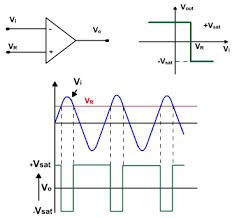
Opamp as comparator (1)

Differential Amp

Integrating Amp
Differentiating Amp


Signal conditioning: Filtering (1)


The function of the signal conditioning circuits include the following items: Signal amplification (opamp), Filtering (opamp), Interfacing with μP (ADC), Protection (Zener & photo isolation), Linearization, Current – voltage change circuits, resistance change circuits (Wheatstone bridge), error compensation .
Operational Amplifiers
Operational amplifiers are the basic element of many signal conditioning modules.

- Generally the opamp has the following properties
- Gain: being of the order greater than 100000
- ideally = infinite
- Input impedance:
- ideally infinite
- output impedance: ideally zero; practical values 20-100 Ω
Opamp Circuit Configurations (1)
- Inverting Op-amp
- Non- inverting Op-amp

- Voltage follower
- Voltage comparator

Opamp as comparator (1)
The output indicates which of the two voltages is high (V1 or V2).
When used with no feedback connection.
If the voltage applied to v1 is greater than V2 then the output is constant voltage equal to (-10V) if (V2>V1) then the output is constant voltage =(+10V). This can be used inthe following example:


Opamp as comparator (2)
The circuit is designed to control temperature with a certain range. When the temp. is below certain value, the thermistor R1 is more than R2 and the bridge is out of balance, it gives an output at its lower saturation limit which keeps the transistor OFF. When temperature rises and R1 falls the opamp switch to +ive saturation value and switch the transistor ON.
Opamp Circuit Configurations (2)
- Summing Amp


Differential Opamp Circuit Example (3)
The difference in voltage between the emfs of the two junctions of the thermocouple is being amplified. If a temperature difference between the thermocouple junctions of 10
0C produces an emf difference of 530 μV, then the values of R1 and R2 can be chosen to give a
circuit with an output of 10mV.


Opamp Circuit Configurations (4)


- Voltage to current
- current to voltage
Instrumentation Amplifier
It is available as single IC is designed to have:
- High input impedance (300M ohm)
- High common mode rejection gain (more than 100 dB)
- High voltage gain
Signal conditioning: Wheatstone Bridge
One of the most used signal conditioning circuit. It can be used to convert a resistance change to a voltage change

Signal conditioning: PROTECTION
• Normally protection is provided against high current and high voltage which may damage the
Important components.
• Examples of protection in mechatronics:
• Series resistor to limit line current
• Fuse to break if the current does exceed a safe level
• Zener diode circuit to protect against high voltage and wrong polarity.
• Optoisolator to isolate circuits completely
Important components.
• Examples of protection in mechatronics:
• Series resistor to limit line current
• Fuse to break if the current does exceed a safe level
• Zener diode circuit to protect against high voltage and wrong polarity.
• Optoisolator to isolate circuits completely
Protection: Zener Diode
• Zener diodes operate in the breakdown region.
• Zener diodes have a specified voltage drop when
they are used in reverse bias. So normally used for
voltage regulation in reverse bias
• Zener has the ability to maintain a nearly constant
voltage under conditions of widely varying current.
Signal conditioning: Filtering (1)
• Filtering is the process of removing a certain band
of frequencies from a signal and permitting others
to be transmitted.
• The Pass Band: the range of frequencies passed by
the filter
• The Stop Band: the range not passed by the filter.
• CUT OFF frequency: the boundary between
stopping and passing
Technically CUTOFF frequency is defined as the frequency
at which the output voltage is 70.7% of that in the pass
band.
Signal conditioning: Filtering (2)
Characteristics of ideal filters:
- (a) low-pass filter
- (b) high-pass filter
- (c) band-pass filter
- (d) band-stop filter

Signal conditioning: Filtering (3)
Passive Filters made up using only resistors, capacitors and inductors
Active filters involve an operational amplifier
- Low-pass filter:
- passive
- active using an operational amplifier
#IPECElectronics#CoreElectronics#Signal_Conditioning


0 comments:
Post a Comment